
Project · Rooms and HVAC airflow
A real clinic floor. 90 real diffusers. Where does the cold air land?
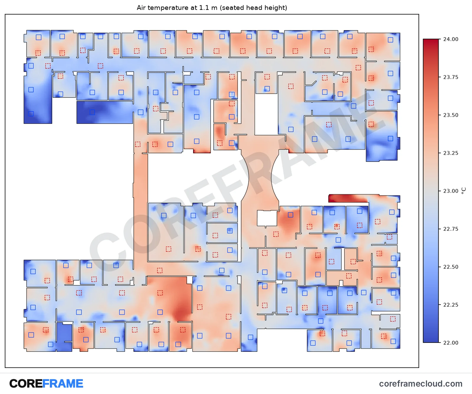
We took a real building model with its HVAC drawn in, and ran the air on a whole floor. Every diffuser sits where the designer put it and blows its design airflow. The rooms are comfortable at head height. At the ankles, the small rooms are draughty.
An indicative, automated first-pass study. Read what that means below.
The result
Comfortable at the head. Draughty at the feet.
23.0 °C
Average air temperature in the occupied rooms. Most of the floor sits between 22.5 and 23.5 °C.
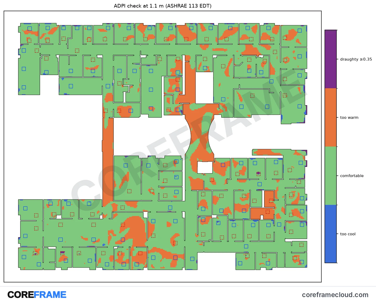
93 %
ADPI (ASHRAE 113) over the floor. 56 of 59 occupied rooms reach 80 % or more.
−0.28
PMV (ISO 7730): a touch on the cool side of neutral, inside the comfortable band.
15 %
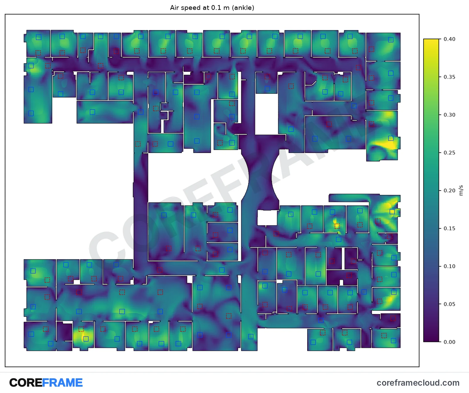
Of the floor has air faster than 0.25 m/s at ankle height. That is the finding.
Measured over the 59 occupied rooms, half a metre in from the walls.
The finding
In the small rooms, the jet hits the wall and comes back along the floor.
The treatment rooms on this floor are about 3 × 3.5 m, each with a four-way ceiling diffuser. Cold air leaves the diffuser along the ceiling. In a room that small it reaches the wall before it slows down, drops down the wall and runs back across the floor.
The temperature is right and the averages look good. But a patient on a chair or a dentist at the chairside feels it at the ankles. 15 % of the floor has air faster than 0.25 m/s at 0.1 m. That is what you would check on a design review: diffuser type and size, throw, and where it sits in the room.
The building
A real clinic, with its HVAC drawn in.
- Building
- A real two-storey clinic, 44,800 sq ft, exported from Revit
- HVAC in the model
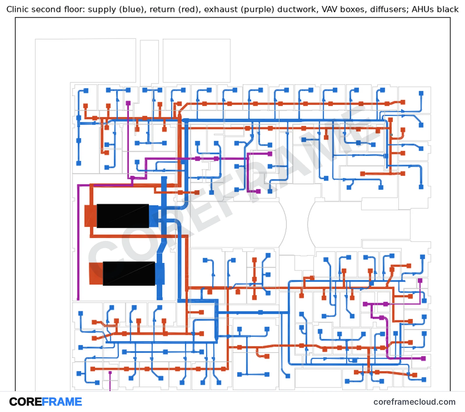
- Ducts, VAV boxes, air handlers and diffusers, with the design airflow on each diffuser
- Floor studied
- Second floor, 18,500 sq ft
- Air volume
- 100 rooms and corridors, 14,500 sq ft of air
- Supply
- 90 real ceiling diffusers at their design flows
- Extract
- 80 return and exhaust grilles in their real positions
- Heat
- A heat load in every room
The model is the buildingSMART Medical-Dental Clinic, an openly licensed sample. Credit and licence are at the end of this page.
The run
One automated run, model in, maps out.
- Mesh
- 1.9 million cells
- Solver
- OpenFOAM, steady, buoyant, 3,000 iterations
- Run time
- 5.1 hours on our own machine in Bengaluru
- Outputs
- Temperature, air speed, ADPI, PMV and draught maps, plus a table for every room
The rooms, doors, diffusers, grilles and their airflows were read from the building model. Nobody drew the floor by hand.
The maps
What the floor looks like.
What this is, and what it is not
An indicative first pass, not an engineering sign-off.
- Coarser mesh. A whole floor at 1.9 million cells is coarser than the level we validate single rooms at.
- Derived loads. Each room's heat load was worked back from its design airflow, not taken from a load calculation.
- Simple diffuser model. Each diffuser blows its design flow through its face, without the maker's throw data.
- Not validated. Rooms and HVAC airflow is not on sale yet. We release it once it passes our validation cases.
For an engineering-grade study we would add:
- A finer mesh on a zone. A group of rooms or one open-plan area meshed at the density we validate single rooms at, not a whole floor at a coarser one.
- Your real loads. Room loads from your load calculation, or people and watts per room, in place of loads derived from the design airflows.
- Your diffusers' data. The make and model of each diffuser, so the jet leaves the ceiling at the throw the maker publishes.
- Envelope for perimeter rooms. Window and wall surface temperatures, so rooms on the façade see the sun and the glass.
- A mesh check. One representative room run on two meshes, to show the answer does not change with the grid.
What it already shows is useful: where the jets go, which rooms are slow or warm, and where the draught risk is. All from the design data, before anything is built.
Ducts and pipes: live today
Pressure drop and loss coefficient for a duct run, a transition or a fitting, from one STL. PDF report, 3D viewer and the data files.
Start a duct jobHave a floor you want checked?
Rooms and HVAC airflow is coming soon. Send us an IFC with spaces and the HVAC model, or plans with a diffuser schedule, and tell us what you need to know.
Talk to usBuilding model credit.“Medical-Dental Clinic” from BSI (2020) “Medical-Dental Test Files,” buildingSMART International, github.com/buildingsmart-community/Community-Sample-Test-Files, licensed under Creative Commons Attribution 4.0 International (CC BY 4.0). Modified: simulated by Coreframe. The second floor was extracted from the IFC model, its rooms joined into one air volume, and its diffusers and grilles used as the airflow inputs for a CFD run. The maps on this page are Coreframe's results, not part of the original files.