
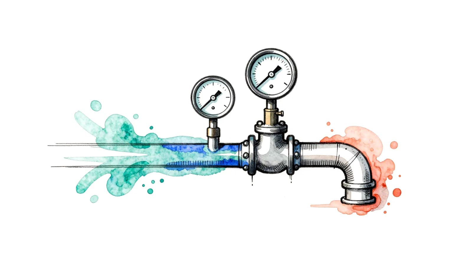
Pressure drop in a duct or pipe is the friction loss along the straight runs, from the Darcy–Weisbach equation, plus a loss for every fitting, from a loss coefficient K. For straight runs and standard fittings that hand calculation is fast and good enough. When a fitting is not in any table, or fittings sit close together, the hand calculation can only guess the biggest loss in the system, and a CFD run of the actual geometry is the better route, provided it shows converged residuals, a resolved wall layer and a mesh that no longer changes the answer.
The basics
What pressure drop is made of
Fluid loses pressure in two ways. Along every metre of straight pipe or duct, friction at the wall takes a steady toll (the major loss). At every bend, tee, reducer, damper or valve, the flow separates and swirls and loses a lump more (the minor loss, which is often not minor at all).
Darcy–Weisbach plus fittings
ΔP  f · (L / D) · ρv²/2  +  ΣK · ρv²/2
f   Moody chart, Colebrook or Haaland
K   handbook tables, one per fitting
Worked example
The hand calculation
Water at 4 m/s in a 50 mm pipe, about 20 °C.
| Step | Value | How |
|---|---|---|
| Reynolds number | Re ≈ 199,600 | ρvD/μ with ρ = 998 kg/m³, μ = 1.0 mPa·s: fully turbulent |
| Friction factor | f ≈ 0.0205 | Haaland, commercial steel ε = 0.045 mm (Colebrook gives 0.0206) |
| Dynamic pressure | ρv²/2 ≈ 7.98 kPa | 998 × 4² / 2 |
| Straight pipe | ≈ 3.3 kPa per metre | f / D × ρv²/2 |
| One 90° elbow | ≈ 2.4 kPa | K = 0.3 taken as an example; handbook values vary widely with radius and make |
| 10 m of pipe and two elbows | ≈ 37.5 kPa | (0.0205 × 10 / 0.05 + 2 × 0.3) × 7.98 kPa: 32.7 kPa of friction, 4.8 kPa of fittings |
The limit
Where the hand calc runs out
K tables are measured on standard fittings, one at a time, with long straight runs before and after. Real systems break those assumptions:
- fittings that are not in any table: custom transitions, offsets, plenums, odd branch angles;
- fittings bolted close together, where the swirl from one changes the loss in the next;
- a quoted range so wide (a factor of two is common) that the total is a guess.
When the fitting is not in the table, the hand calc can only guess the biggest loss in your system.
Why engineers reach for CFD
The CFD route
Geometry, mesh, solve, then check
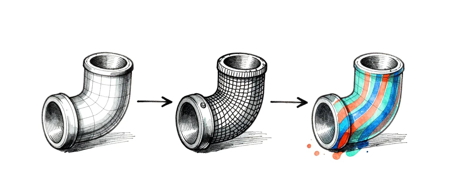
A CFD number is only as good as three checks. The residuals must fall below their target, so the answer has stopped changing. The cells at the wall must be thin enough (y+ ≈ 1) to resolve the boundary layer where the friction is made. And the answer must not move when the mesh is refined, which is what a mesh independence study measures.
wall layers on every Coreframe mesh by default
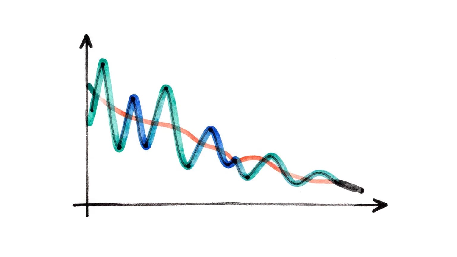
On our own validation cases, the friction factor in a straight pipe matched the Haaland/Colebrook correlation to about 1–5 %. That is the check to ask of any CFD provider: show the straight-pipe case against the textbook before you trust the fitting.
Choosing
Hand calc or CFD: which one when
| Hand calc | CFD | |
|---|---|---|
| Straight runs, standard fittings | Yes: fast and good enough | Rarely worth it |
| Fitting not in any table | A guess | Yes |
| Fittings close together | Underestimates the interaction | Yes, modelled together |
| You need to see why | No | Flow paths, separation, hot spots |
| Time | Minutes | Hours, plus checks |

Coreframe runs pressure drop CFD for duct and pipe STLs: pre-processing and mesh check first, then a quote, then the run and a report.
Questions
How do you calculate pressure drop in a pipe?
Add the friction loss along the straight runs, f · (L/D) · ρv²/2 from the Darcy–Weisbach equation with f from Colebrook or Haaland, to a loss K · ρv²/2 for each fitting, with K from handbook tables.
When is CFD better than a hand calculation for pressure drop?
When a fitting is not in any K table, when fittings sit close enough together to affect each other, or when you need to see where the loss is made. For straight runs and standard fittings, the hand calculation is usually good enough.
How do I know a CFD pressure drop is right?
Ask for three things: residuals under their target (a converged run), wall layers fine enough to resolve the boundary layer (y+ ≈ 1), and evidence that refining the mesh no longer changes the answer (a mesh independence study with the grid convergence index). A straight-pipe case checked against Colebrook or Haaland is a good first test of any provider.
Try it on your own project
Open your heaviest scene on an RTX 5080.
New accounts: your first top-up of ₹1,000 buys 8 hours on an RTX 5080, to use within 30 days. Sign up with an email and a WhatsApp code, no ID documents. International cards work.